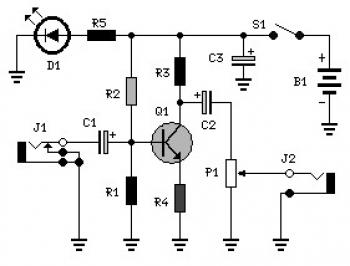
The following circuit has a maximum gain of around 22 dB (voltage gain). The frequency response of the amplifier is determined mostly by the value of just a couple of components, primarily C1 and R1. The values of the circuit diagram present a response of ±3.0 dB from about 120 Hz to higher than 20,000 Hz.In fact, the frequency response is ruler flat starting from about 170 Hz to more than 20,000 Hz; it's the low end that deviates from a flat frequency response.

No comments:
Post a Comment